Introduction
High manganese steel liners are alloy steel materials with a manganese content of 10% to 15% and a carbon content of 0.90% to 1.50%. They are mainly used in mining machinery, ball mills, loaders, excavators, cutting tools, bulldozer buckets and blade plates. Its surface hardness can be increased from HRC20 to 25 to over HRC40 through work hardening.This material is mostly formed by processes such as sand casting and metal mold casting, and its performance is enhanced through water toughness treatment. When installing, fill the gap with cement mortar and fix the bolts with dust-proof gaskets.
Features
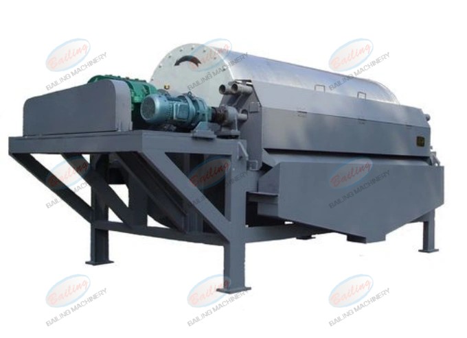
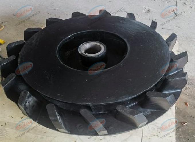
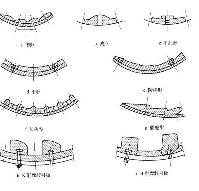
The liner of the ball mill mainly serves to protect the inner wall of the anchor hoist. Making the liner of the ball mill into different shapes can improve the grinding effect of the ball mill and enhance its working efficiency.
- Flat type ball mill liner, with a smooth surface, is suitable for installation in the fine grinding chamber.
- The strip-shaped ball mill liner is suitable for the coarse grinding chamber and for ball mills with low rotational speeds.
- The stepped ball mill liner is superior to the pressure strip liner and is suitable for installation in the coarse grinding chamber.
- The small corrugated liner has small wave peaks and pitches, making it suitable for fine grinding bins and coal mills.
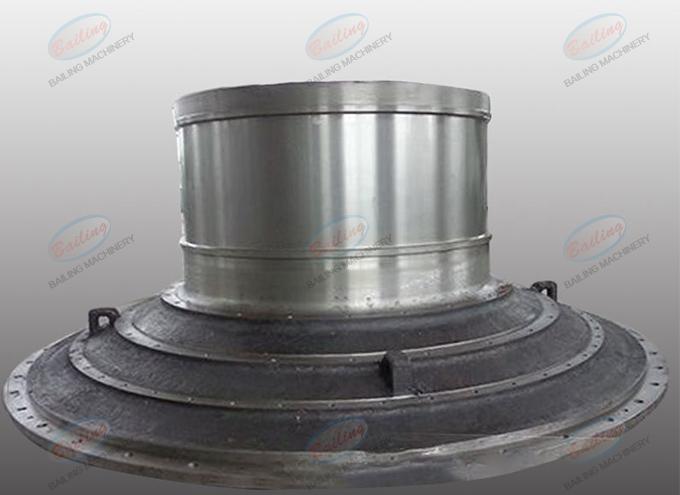
- The end cover liner is installed on the grinding head end cover or the cylinder end cover to protect the end cover from wear.
- The annular groove liner has arc-shaped grooves cast on the T-working surface of the liner. After installation, it forms annular grooves, which are suitable for the first and second chambers of multi-chamber mills and can be used in both dry and wet mills
- The ideal state of the classification liner for the grinding operation of the ball mill should be that large-particle materials are impacted and crushed by large-diameter grinding media. That is, large-diameter grinding media are provided in the feeding direction of the mill. As the material gradually decreases towards the discharging direction, the grinding media should also decrease in sequence.
Parameter
| Model | Rotational speed(r/min) | Balls weight(t) | Feeding size(mm) | Output size(mm) | Capacity(t/h) | Motor power(kw) | Weight(t) |
| Ф900×1800 | 42 | 1.4 | ≤20 | 0.075-0.89 | 0.65-2 | 18.5 | 3.6 |
| Ф900×2100 | 41 | 1.7 | ≤15 | 0.075-0.83 | 0.7-3.5 | 15 | 3.9 |
| Ф900×3000 | 41 | 2.7 | ≤20 | 0.075-0.89 | 1.1-3.5 | 22 | 4.5 |
| Ф1200×2400 | 36 | 3.5 | ≤25 | 0.075-0.6 | 1.5-4.7 | 30 | 11.5 |
| Ф1200×2800 | 31 | 6.8 | ≤25 | 0.075-0.6 | 1.5-5 | 37 | 13 |
| Ф1200×4500 | 32 | 5.5 | ≤25 | 0.074-0.4 | 1.6-5.8 | 55 | 13.8 |
| Ф1500×3000 | 31 | 6.8 | ≤25 | 0.074-0.4 | 2-7 | 75 | 17 |
| Ф1500×4500 | 27 | 10.5 | ≤25 | 0.074-0.4 | 3.5-8 | 110 | 21 |
| Ф1500×5700 | 27 | 15 | ≤25 | 0.074-0.4 | 3.5-10 | 130 | 24.7 |
| Ф1830×3000 | 26 | 13 | ≤25 | 0.074-0.4 | 4-12 | 160 | 28 |
| Ф1830×3600 | 26 | 15 | ≤25 | 0.075-0.4 | 5-13 | 160 | 33.5 |
| Ф1830×4500 | 26.5 | 17 | ≤25 | 0.075-0.6 | 5.5-20 | 185 | 35 |
| Ф1830×7000 | 26 | 25 | ≤25 | 0.074-0.4 | 6.5-22 | 210 | 36 |
| Ф2100×3600 | 24 | 21 | ≤25 | 0.074-0.4 | 6.5-22 | 185 | 46.8 |
| Ф2200×5500 | 21 | 30 | ≤25 | 0.074-0.4 | 10-20 | 245 | 48.5 |
| Ф2200×6500 | 21.7 | 35 | ≤25 | 0.074-0.4 | 14-26 | 380 | 52.8 |
| Ф2200×7500 | 21 | 33 | ≤25 | 0.074-0.4 | 16-30 | 380 | 56 |
| Ф2400×3000 | 20.6 | 30 | ≤25 | 0.075-0.4 | 15-50 | 245 | 59 |
| Ф2400×4500 | 21 | 33 | ≤25 | 0.074-0.4 | 15-60 | 380 | 65 |
| Ф2700×3600 | 20.6 | 39 | ≤25 | 0.074-0.4 | 20-70 | 400 | 91.3 |
| Ф2700×4000 | 20.7 | 40 | ≤25 | 0.074-0.4 | 20-80 | 400 | 94 |
| Ф2700×4500 | 20.7 | 48 | ≤25 | 0.074-0.4 | 20-90 | 430 | 102 |
| Ф3200×4500 | 18 | 65 | ≤25 | 0.075-0.4 | according to the process conditions | 800 | 137 |