Description
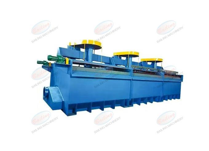
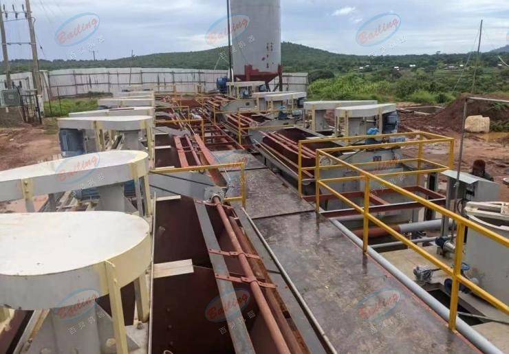
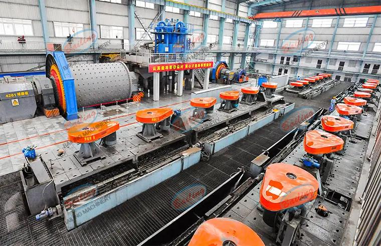
The XJ type (also known as Type A or XJK type) flotation machine, also called the mechanical agitation flotation machine for mining, is an air self-priming mechanical agitation flotation machine with a radial impeller. This mechanical flotation machine has been improved, its basic structure remains unchanged. In recent years, it has been replaced by some new types of flotation machines. Due to historical reasons, it was applied earlier. It is still widely used at present and has long formed a series of products.
Advantages
The XJ type flotation machine features strong stirring force, low reagent consumption, the ability to handle coarse-grained and denser ores, adaptability to complex processes, wide application, and stable indicators.
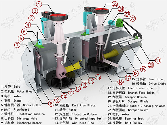
Equipment structure
The cover plate is equipped with 18 to 20 guide vanes (also known as stators). These blades are arranged at an Angle of 60° to the radius and are used to guide the slurry flow thrown out by the impeller. Between the two guide vanes on the cover plate, 18 to 20 circulation holes are opened for the circulation of pulp, thereby increasing the aeration volume.
The gap between the impeller and the guide vanes of the cover plate is generally 5 to 8mm. If it is too large, it will have an adverse effect on the suction volume and power consumption. Usually, the impeller, cover plate, main shaft, air inlet pipe and air pipe and other aeration and stirring parts are assembled into an integral component. This enables the impeller and cover plate to be concentrically assembled, ensuring that the gap between the impeller and the guide vanes of the cover plate meets the requirements and facilitating maintenance and replacement.
At the lower part of the air cylinder, there is a circulation hole for regulating the slurry circulation volume, and the circulation volume is controlled by a gate plate.
Working principle
The XJK type flotation machine forms a unit with every two tanks. The first tank is equipped with a slurry inlet pipe to draw in the pulp, also known as the suction tank or suction tank. The second slot is either a self-flowing slot or a direct current slot. Between the first tank and the second tank, there is an intermediate chamber where the pulp is connected below. The impeller is installed at the lower end of the main shaft, and there is a pulley at the upper end of the main shaft, which is driven to rotate by an electric motor. Air is drawn in through the air intake pipe. The horizontal level of the pulp in each group of flotation cells is regulated by the gate. A cover plate and an air cylinder (also known as a vertical pipe) are installed above the impeller. Holes are opened on the air cylinder for installing the slurry inlet pipe, the medium-ore return pipe or for slurry circulation. The size of the holes can be adjusted by the pull rod.
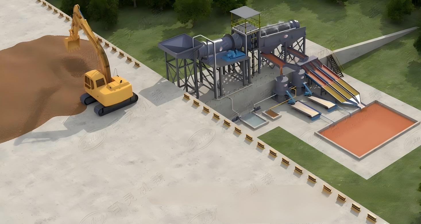
3D drawing
Parameter
| Type | Model | Volume(m³) | Impeller diameter(mm) | Capacity(m³/min) | Motor power(kw) | Chute weight(kg) | Chute dimension(mm) | |
| Stirring motor | Scraper motor | |||||||
| XJseries flotation machine | XJ-0.13 | 0.13 | 200 | 0.05-0.16 | 1.5 | 0.55 | 1272(4cells) | 1120×1140 |
| XJ-0.23 | 0.23 | 250 | 0.12-0.28 | 1.5 | 0.55 | 1558(4cells) | 1190×1238 | |
| XJ-0.35 | 0.35 | 300 | 0.15-0.5 | 2.2 | 0.55 | 1720(4cells) | 1350×1327 | |
| XJ-0.62 | 0.62 | 350 | 0.3-0.9 | 3 | 1.1 | 3041(4cells) | 1535×1760 | |
| XJ-1.1 | 1.1 | 500 | 0.6-1.6 | 5.5 | 1.1 | 5204(4cells) | 1970×2088 | |
| XJ-2.8 | 2.8 | 600 | 1.5-3.5 | 11 | 1.1 | 9295(4cells) | 2450×2295 | |
| XJ-5.8 | 5.8 | 750 | 5—7 | 22 | 1.5 | 13597(4cells) | 3250×2485 | |