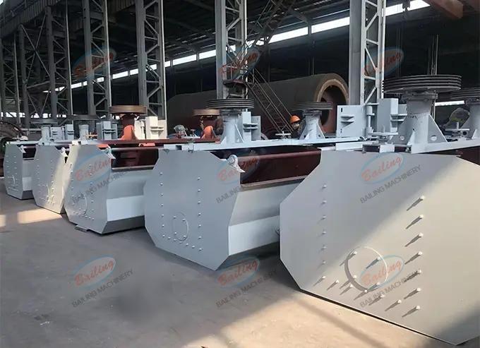
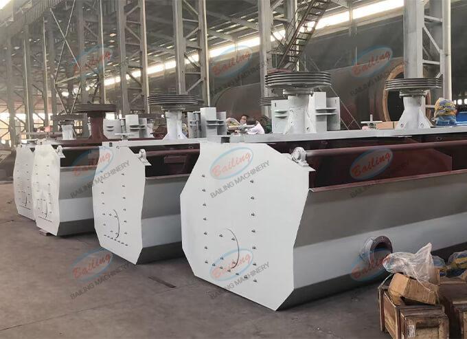
Description
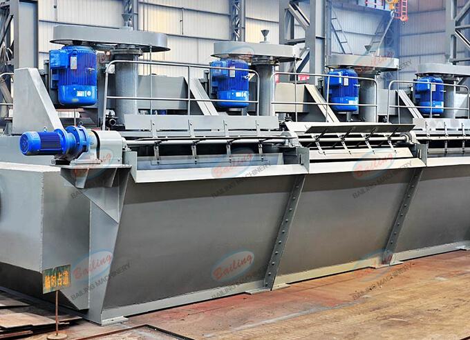
SF flotation machine is suitable for the separation of non-ferrous and ferrous metals, and can also be used for the separation of non-metals such as coal fluorite and talc. The flotation machine is driven by an electric motor and a V-belt to rotate the impeller, generating a centrifugal force to create negative pressure. On the one hand, it sucks in sufficient air to mix with the pulp; on the other hand, it stirs the pulp to mix with the reagents, and at the same time refines the foam, causing the minerals to adhere to the foam and float to the surface of the pulp to form mineralized foam. Adjust the height of the gate plate to control the liquid level and make the useful foam be scraped out by the scraper.
Advantages
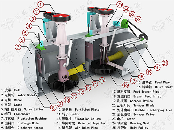
Structure drawing
The flotation machine is mainly composed of the rotor, guide impeller, partition plate, scraper, scraper drive and other parts
Working principle
When the SF type flotation machine is in operation, the motor drives the main shaft through the V-belt, causing the impeller at its lower part to rotate. The main feature of this flotation machine is reflected in the impeller. The impeller is equipped with backward-inclined double-sided blades, which can achieve double circulation of the slurry in the tank.
When the impeller rotates, the pulp in the upper and lower impeller cavities is thrown to the periphery under the action of the main shaft and blades, generating centrifugal force, thus creating negative pressure zones in the upper and lower impeller cavities. Meanwhile, the pulp on the upper part of the cover plate is sucked into the upper impeller cavity through the circulation holes on the cover plate, forming an upward circulation of the pulp. The slurry thrown out of the lower impeller cavity is heavier in specific gravity than the three-phase mixture thrown out by the upper blades, thus increasing the centrifugal force and slowing down the attenuation of the movement speed. Moreover, it exerts an additional driving force on the three-phase mixture thrown out by the upper blades, increasing its centrifugal force and thereby enhancing the vacuum degree in the upper impeller cavity, playing an auxiliary suction role. When the lower blade throws out the pulp in all directions, the pulp at its lower part replenishes to the center, thus forming a lower circulation of the pulp. The air is drawn into the upper impeller cavity through the suction pipe and the central cylinder, where it mixes with the drawn pulp to form a large number of fine bubbles. After being stabilized by the cover plate, the bubbles are evenly dispersed in the tank to form mineralized bubbles. The mineralized bubbles rise to the foam layer and are scraped out by the scraper to form the foam product.
3D drawing
Parameter
| Type | Model | Volume | Impeller diameter | Capacity | Motor power(kw) | Chute weight | |
| (m³) | (mm) | (m³/min) | Stirring motor | Scraper motor | (kg) | ||
| SFseries flotation machine | SF0.37 | 0.37 | 300 | 0.2-0.4 | 2.2 | 0.75 | 445 |
| SF0.7 | 0.7 | 350 | 0.3-1.0 | 3 | 0.75 | 600 | |
| SF1.0 | 1 | 400 | 0.45-1.1 | 5.5 | 0.75 | 978 | |
| SF1.2 | 1.2 | 450 | 0.6-1.6 | 5.5 | 0.75 | 1240 | |
| SF2.0 | 2 | 550 | 1.5-3.0 | 7.5 | 1.1 | 1879 | |
| SF2.8 | 2.8 | 550 | 1.5-3.5 | 11 | 1.1 | 2242 | |
| SF4.0 | 4 | 650 | 2.0-4.0 | 15 | 1.5 | 2660 | |
| SF8.0 | 8 | 760 | 4.0-8.0 | 30 | 1.5 | 4043 | |
| SF-16 | 16 | 850 | 5.0-16 | 45 | 1.5 | 7415 | |
| SF-20 | 20 | 730 | 5.0-20 | 30*2 | 1.5 | 9828 | |