Description
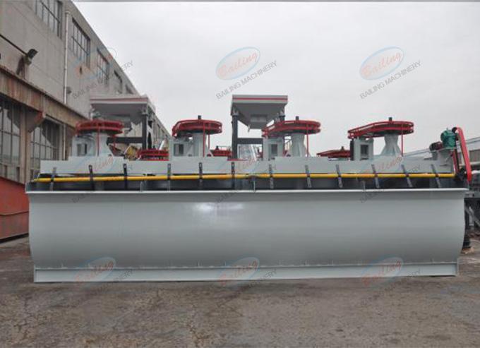
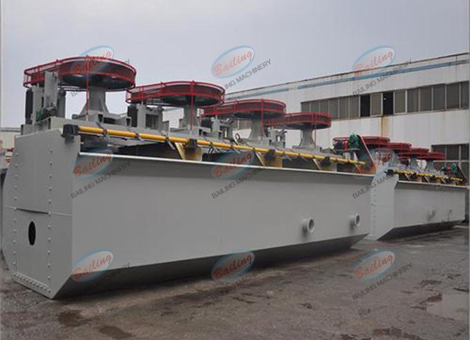
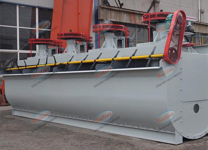
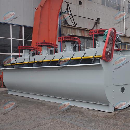
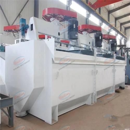
The KYF flotation machine is composed of components such as impellers, stator, U-shaped tank bodies, hollow main shafts and air distributors. The tank bodies are available in two forms: pulp type and column type. The volume of a single tank ranges from 1 to 320 cubic meters and is equipped with an automatic control system for liquid level and air volume.
Advantages
- The impeller of the flotation machine is a conical impeller with blades inclined backward at an Angle. It has strong stirring capacity and a simple structure.
- A multi-hole cylindrical air distributor is installed in the impeller cavity, ensuring uniform air dispersion and good air-slurry combination.
- The impeller diameter is small, the circumferential speed is low, and the power consumption is small, which can save 30-50% of energy.
- The U-shaped tank body is adopted, resulting in less tailings deposition.
- Mechanical stirring type, cannot self-draw air, cannot self-draw pulp, and the operation room needs to be configured in steps.
Working principle
When the impeller of the KYF type aerated mechanical agitation flotation machine rotates, the pulp in the tank is drawn into the space between the impeller blades from the bottom of the tank through the periphery and the lower end of the impeller. Meanwhile, the low-pressure air supplied by the blower enters the air distributor in the impeller cavity through the air duct, air regulating valve and hollow main shaft, and then enters the space between the impeller blades through the holes around the distributor. After the pulp and air are thoroughly mixed between the impeller blades, they are discharged from the periphery of the upper half of the impeller. The discharged pulp flows obliquely upward and is stabilized and oriented by the stators installed obliquely above the periphery of the impeller, then dispersed throughout the entire tank. Mineralized bubbles rise to the surface of the tank to form foam. The foam flows into the foam tank by itself, and the pulp returns to the impeller area for recirculation. The other part enters the lower tank through the flow holes on the tank wall for re-separation.
Parameter
| Model | Effecive volume(m3) | Capacity(m3/min) | Impeller diameter(mm) | Impeller revolutions(r/min) | Blower air pressure(kPa) | Maximum inflation volume(m3/min) | Stirring motor power(kw) | Scraper motor power(kw) | Chute weight(kg) |
| KYF-1 | 1 | 0.2 ~1 | 340 | 281 | > 12.6 | 2 | 4 | 0.75 | 903 |
| KYF-2 | 2 | 0.4 ~2 | 410 | 247 | > 14.7 | 2 | 5.5 | 1.1 | 1419 |
| KYF-3 | 3 | 0.6 ~3 | 480 | 219 | > 19.8 | 2 | 7.5 | 1.5 | 1885 |
| KYF-4 | 4 | 1.2 ~4 | 550 | 200 | > 19.8 | 2 | 11 | 1.5 | 2206 |
| KYF-8 | 8 | 3.0 ~8 | 630 | 175 | > 21.6 | 2 | 15 | 1.5 | 3984 |
| KYF-10 | 10 | 4.0 ~10 | 630 | 192 | > 21.6 | 2 | 22 | 1.5 | 4406 |
| KYF-16 | 16 | 4.0 ~16 | 740 | 160 | > 25.5 | 2 | 30 | 1.5 | 5900 |
| KYF-24 | 24 | 4.0 ~24 | 800 | 150 | > 30.4 | 2 | 30 | 1.5 | 7500 |
| KYF-38 | 38 | 10.0 ~38 | 880 | 139 | > 34.3 | 2 | 45 | 1.5 | 10300 |